
External clock generation on RTX 50 series
- PickleRick

- Jun 2
- 6 min read
Pushing past Nvidia imposed performance limitations on RTX 5090
By PickleRick of Xtreme Systems Credits to Turbogear of Xtreme Systems, this would not have been possible without his expertise and RF engineering background
Special thanks to ElmorLabs

Brief history Starting in the late 1970s, thru the 80s, and into the early 90s, many of the first overclocks were achieved thru crystal swapping. Systems from this time period often had no provisions for altering clock speeds via software or jumpers. People who wished to push past the factory frequency of these chips had to do so via changing the reference clock that was used to drive the clock speed of their chips. In some cases, overclocks of up to 16,000% were achieved via these methods.
Throughout the 1990s, motherboard manufactures started including the option to overclock via jumpers, and eventually software control of the FSB clock speed, memory straps, etc.
Throughout the early 2000s up until today, software controls enabling us to overclock graphics cards have been for the most part pretty open, thru software clock speed tools, vBIOS editors, voltage tools, etc. Starting with the Pascal series GPU's (GTX 10 series), vBIOS editing was no longer an option for most consumers, leaving us with just core clock and memory clock adjustment, and in some cases voltage and power limit changes thru XOC vBIOS and related software tools. As time went on, the capability of the tools given to us were slowly scaled back.
Today, on high end RTX 50 series cards, we no longer have control to push video memory clock speeds to their limit. And hidden clocks such as crossbar which control the interconnect speed (akin to Intel's D2D, ring bus, or AMD's FCLK) can only be altered to a point thru cross-flashing vBIOS.
Theory
On high-end Nvidia GPUs, such as the RTX 5090, many of us overclocking are binning chips for crossbar clock in a 100Mhz range, and stock voltage in a 80mV range as set by the VF curve NVIDIA assigns. For reference, a RTX 5090 with a xBAR clock of 2600 Mhz is considered poor, whereas a chip that presents a xBAR clock of 2700 Mhz, that can also sustain high gpu core clocks, is considered golden. So the hypothesis was, what if we could alter both the VRAM and xBAR clocks to truly push these chips to their limits?
Testing/Issues
Turbogear and I spent several weeks of trial and error trying to get a product called the Elmor External Clock Board (ECB) working on 50 series GPUs. The results of the first benchmarks after these modifications were evidently beyond our expectations, passing several LN2 scores with just a budget water chiller.
In the mod’s current state it is still very much a work in progress with some issues, however, it is working sufficiently to produce consistent high-scoring 3D graphics card benchmark results. If wire routing of the mod is not optimal, simply standing up near or moving quickly near the GPU can cause it to crash, or in some cases never post at all.
For the RTX 50 series GPUs, the phase-locked loop (PLL) is expecting a ~1.15 VPP AC coupled, sinusoidal/analog waveform as input. The Elmor ECB produces a 1.6 VPP AC coupled square/digital waveform on its XTAL out connector. Signal integrity over a normal wire can also be an issue, many early attempts failed due to these challenges. Tuning the circuit to function correctly is difficult due to the PLL contained within the GPU core itself altering the signal, as it has properties undocumented by any specification accessible to the public. We needed to reduce the VPP of the signal to a safe level as to not damage the PLL, while also ensuring that the GPU is able to post. We tried several combinations of voltage divider circuits, RF attenuators, and low pass filters. Each of these components helped in some ways but created new issues.
Conclusively, so far with Elmor ECB what has worked best is utilizing a 20 ohm series resistor, 1800mV output and minimum drive strength. This creates a somewhat triangular waveform that appears far from ideal on an oscilloscope, however, still allowing the card to Post and Bench effectively. While producing an in-circuit VPP of 1.2v which is within reason. Attempts to send a clean signal into the card with external filters, resistor divider circuits, and RF attenuators had mixed success. A low pass filter makes the signal look great on a scope, and the card does post, but reflection issues lead to VPP changing with frequency to numbers far out of spec. An RF attenuator placed after the low pass fixed this but prevented post.
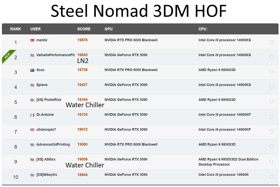
Results
Among the cards tested so far, we were able to achieve the equivalent of what would be +5467 on the memory slider in MSI afterburner for the RTX 5090, and a crossbar clock of around 2920 Mhz. The resulting scores exceeded our expectations, I knew this would help increase score, but did not expect this large of a gain.
Initially I started off with low core clock offset testing and matching effective memory clocks to the normal limit of the specified vBIOS. On port royal I saw a gain of about 500 points from raising crossbar, And another 200 ish points from pushing memory beyond the typical limits. After bringing coolant temps down another 7c, and pushing clocks up, I was able to gain 1500 points in port royal over my previous best score.
NVIDIA reported clock speeds will be skewed, as they are calculated off of a 27 Mhz reference clock. Credits to ASGxx of Xtreme Systems for creating a calculator to easily calculate the real clock frequencies; Which you can find at: https://www.hofrank.com/ecb

How to
DISCLAIMER: I accept no liability whatsoever for any damage, loss, or destruction of hardware including permanent GPU failure resulting from external clock generator (ECB), or any other hardmod modifications described here. This mod still needs a lot of refinement before I would consider it a proper solution. You proceed entirely at your own risk.
Supplies
Elmor ECB
Hot plate
Hot air station
30 awg enamel wire
0603 20 ohm resistor
Kapton tape
Clear/white quick cure UV solder mask (strain relief)
UV curing lamp
SPDT Micro switch or JST-XH connectors.
General soldering equipment/knowledge
Step 1: Remove the factory XTAL oscillator from the GPU using a hot plate, hot air, and some flux. Apply kapton tape to protect the core and memory bga from direct hot airflow.

Step 2: To retain stock operation on a switch or jumper, flip the xtal over horizontally. Create 3 jumper wires. 2 between the ground pads, and one between the XTAL out pads.
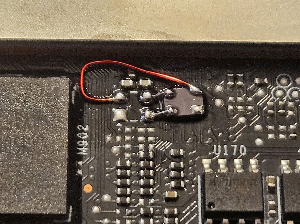
Step 3: Run enamel wires to the XTAL in pad of the GPU PCB, and the remaining pad on the XTAL oscillator itself (coax wire would likely be ideal here, but creates challenges with strain relief, these tiny pads on the GPU PCB are very fragile, and the trace length between the pad and edge of the core is quite small, I think on astral board layout, coax will be required). On the 5090's I modded for use on waterblock/chiller, I ran these wires to a small SPDT switch to help with both strain relief and keeping the wire length short, For use on a LN2 pot I ran these wires to a JST-XH connector instead. Some Relife branded clear/white fast cure UV solder mask was used to help with strain relief for this sensitive pad.

Step 4: Run these wires to either a connector to use as a jumper/input, or a switch. (An RF switch would be ideal here, Turbogear is working on this currently, but it may bring additional challenges) Take care to avoid routing these wires near any inductors or MOSFETs, avoid sharp bends, and keep the wires as short as possible. In our testing wire routing and length was crucial to getting the GPU to post, further proving the point that coax wire would likely be ideal.
Switch method

Jumper method

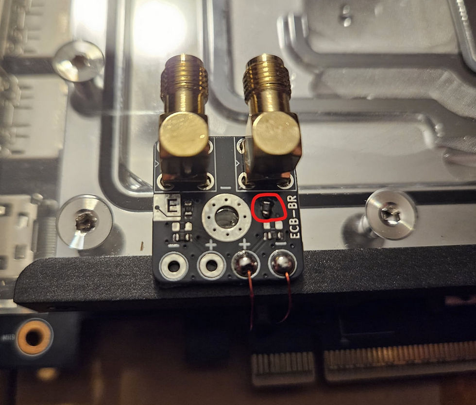
Step 5: Install a 20 ohm 0603 series resistor on the Elmor ECB breakout board, and run the signal and gnd wires to this same board. Once again, take care to keep these wires as short as possible. If using the jumper method, produce a JST-XH jumper to bridge the stock XTAL to the XTAL in pin.
Waterblock with switch install
LN2 jumper install

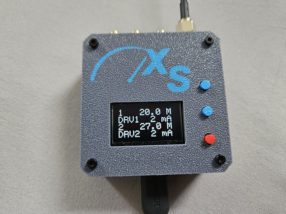
Step 6: Before connecting to the GPU, set the Elmor ECB output 2 to 2ma drive strength, and 1800mv, be very careful not to fat finger the DS option, as this will send high VPP which may damage the PLL located inside the GPU core. Stock XTAL frequency on Nvidia 50 series is 27Mhz. Connect the GPU to the XTAL port on the ECB, and power the ECB before powering on the PC.
In testing we found that you must use HDMI and a monitor that is capable of accepting an out of range signal. This mod overclocks everything on the GPU, such as HDMI, PCIe, xBAR, memory, core, and PWM fan speeds. It is similar to a BCLK OC on a motherboard.
After you have posted, you can adjust the frequency up in steps, up to .3-.4 at a time. More than this can cause stability issues. ECB frequency scales with load temp, cards tested so far have been able to reach 28.7-29.2 depending on bin and temperature.
In testing, some motherboards allowed the GPU to post above 27Mhz no problem, whereas others will instead force CSM mode and/or enablement of integrated graphics.
That's amazing. I thought the 5090 was a stretch but I see that I am mistaken. Kudos. If this works, I would love to purchase service for mine. I have the Astral 5090.
Dude, I am so glad to see this. Old forum member from over 20 years ago. You guys are still effen nuts. Glad to see Fugger's name still there. We have an unlinked connection from back in the Barton 2500/NF-7 days, but i let that go a long time ago...lol (not really)
Great work.
Is it possible that finding and directly replacing it with a compatible 28 MHz or 29 MHz XTAL could be a more practical and simpler solution?
Thank you @PickleRick for a nice article.
As you mentioned the gains are nice but the challenges are big. If one is not careful then killing the card is likely outcome.